|
View the contents of this section using the scrollbar on the right side of the screen. Alternatively you may connect your printer and click on the button below to print out this page. |
| Please contact Malcolm Sutton for Technical Support. |
Common reasons for the provision of Power Factor Correction Capacitors include,
Reducing the load on distribution network components can result in an extension of their useful life. This would improve the integrity of the system. The ability to connect additional load is always of benefit to an expanding company. |
Charges levied by the Electricity Supply Companies are calculated according to an agreed tariff. Some tariffs penalise consumers
for poor power factor. In these cases a reduction in the overall cost of electricity can be achieved by improving the power
factor to a more economic level. Example: A fully loaded 1000kVA transformer supplying a load with a power factor of 0.80 can only supply 800kW of "useful" load. By correcting the power factor to 0.95, an additional 150kW of load may be connected, increasing the "useful" load capacity to 950kW. Alternatively, by correcting the power factor from 0.80 to 0.95, the demand on the supply would be reduced by 158kVA. The consumer would save over £230 per month based on a typical charge of £1.50 per KVA of supply. |
|
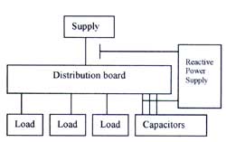
To automatically correct the power factor of a load, a number of capacitors are connected to the supply.
The capacitors are controlled by a microprocessor based relay which continuously monitors the reactive power
demand on the supply. The relay connects and/or disconnects the capacitors to compensate for the reactive power of the total load. This reduces the overall demand on the supply. Systems are manufactured utilising capacitors of either MKP, MKK or MPP/MKV technology. A typical power factor correction system would incorporate a number of capacitor sections (stages) determined by the characteristics and the reactive power requirements of the installation under consideration. |
![]()
Switching stages of 25kVAr are usually employed. Larger sections (e.g. 50kVAr and above) are achieved by cascading a number of smaller sections.
This has the beneficial effect of reducing the inrush current to the capacitors and minimises supply disturbances. Where harmonic distortion
is of concern, appropriate systems are supplied incorporating detuning reactors. |
A Typical Inductive Load![]() |
Under normal operating conditions certain electrical loads
(e.g. induction motors, welding equipment, arc furnaces and fluorescent lighting) draw not only active power from the supply
(kilowatts kW) but also reactive power (reactive KVA, KVAR). This reactive power is necessary for the equipment
to operate correctly but could be interpreted as an undesirable burden on the supply. The demand made by such a load on the supply is outlined in the figure to the left. |
|
Opposing reactive power resulting from the connection of a correctly sized capacitor can compensate for the reactive
power required by the load. This ensures a reduction in the reactive power drawn from the supply. Power Factor Correction is the connection of a capacitor to an inductive load. This achieves a reduction in the total current drawn from the supply and is known as 'PFC' or 'Correction'. A load with an associated capacitor is said to be 'Corrected'. |
The effect of a capacitor on an Inductive Load![]() |
Power Factor Correction (Vector Diagram)![]() |
The Power Factor of a load is defined as the ratio of active power to apparent power
i.e. kW:kVA and is referred to as Cos Ø In the figure to the left the uncorrected power factor of the load is Cos Ø 1 and the corrected power factor is Cos Ø 2 The closer Cos Ø is to unity, the less reactive power is drawn from the supply. |